
1. Work Coordinates (WCS / G54)
Tells the machine controller where the raw material’s front face and centerline sit relative to the machine’s physical home position.
2. Tool Geometry Offsets
Tells the controller the exact physical distance from the reference edge of the tool turret disk to the cutting tip of each individual tool insert.
📐 Setting Work Coordinate System (WCS) Using G54
The standard industry method for finding your Z-axis zero point involves physically touching off the material with a tool and taking a clean face cut.
The Step-by-Step Touch-Off Procedure:
- Load your reference tool (typically a rough turning tool) into the turret.
- Spin the spindle manually in forward rotation (M03) at a safe speed (e.g., 800 RPM).
- Jog the tool close to the front face of the material. Switch your controller handle to fine increment mode (0.01 mm).
- Carefully skim a thin layer off the front face of your material. Do not move the Z-axis after making contact!
- Stop the spindle and jog the tool away cleanly along the X-axis only.
Inputting Values into the Fanuc Offset Page:
- Press the physical OFS/SET button on the machine panel.
- Select the Work soft key on the digital screen to view your coordinate registers.
- Arrow down to highlight the Z-axis entry field under G54.
- Type Z0.0 and then press the MEASURE soft key on the keypad.
⚙️ 3. Tool Geometry Offsets (X & Z Axis Calibration)
Because every tool shanks out at a different length, each tool slot requires its own baseline dimensional offset.
Calibrating the Z-Axis Offset:
- Touch the tip of your tool to the freshly cut front face ( Z0.0 ).
- Navigate to the Offset ➔ Geometry page on the screen. Highlight your specific tool number (e.g., G01 for Tool 1).
- Type Z0.0 on the keypad and press the MEASURE soft key.
Calibrating the X-Axis Offset (The Diameter Method):
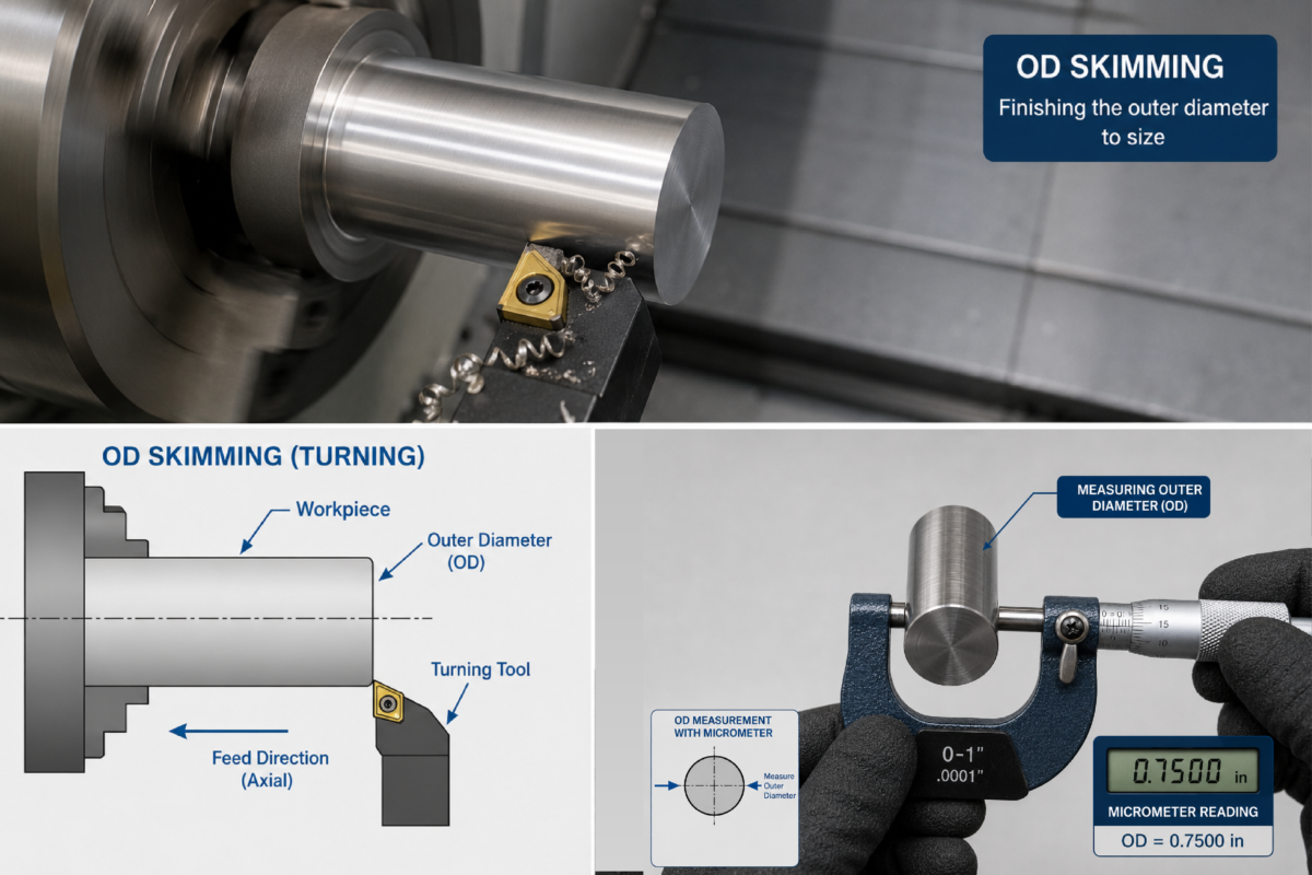
- Jog your tool to the outer diameter (OD) of the spinning raw material and take a light, clean skimming pass along the length.
- Without moving the X-axis, retract the tool out of the cut along the Z-axis positive direction ( +Z ).
- Turn off the spindle and use a digital micrometer or vernier caliper to measure the exact turned outside diameter of the bar stock.
- Go to the Geometry Offset page, highlight your tool number’s X register, type X followed by your exact measured value (e.g., X48.52 ), and press the MEASURE soft key.
🚨
Key Takeaways
G54 sets the absolute part framework; Geometry offsets tell the machine how individual tool lengths vary.
On a turning center, your X-axis centerline (X0.0) is always the physical center of your spinning spindle. You only need to calibrate its shift distance using part diameters.
Never eye-ball a touch-off point. Always use a clean reference skim cut and verify values with calibrated micrometers.