When programming a Vertical Machining Center (VMC), certain operations like drilling, boring, tapping, and reaming are repetitive. Writing full toolpath codes (G01, G00, G02, G03) for each step would be time-consuming.
To simplify this, Fanuc controls (and most CNC controls) use Canned Cycles – pre-programmed subroutines that perform common machining operations with just one command line.
In simple terms – A Canned Cycle is a shortcut command that tells the machine how to drill, bore, or tap, without writing long G-code sequences.
Common Fanuc Canned Cycles in VMC
Here are the most widely used G-codes for drilling operations in VMC:
| G-Code | Description |
|---|---|
| G73 | High-Speed Peck Drilling Cycle |
| G74 | Left-Hand (Reverse) Rigid Tapping Cycle |
| G76 | Fine Boring Cycle |
| G81 | Simple Drilling Cycle |
| G82 | Drilling with Dwell Cycle |
| G83 | Peck Drilling Cycle (Deep Hole Drilling) |
| G84 | Tapping Cycle (Rigid / Floating Tap Holder) |
| G85 | Boring Cycle (feed in, feed out) |
| G86 | Boring Cycle (feed in, rapid out) |
| G87 | Back Boring Cycle |
| G88 | Boring Cycle (dwell, manual retract) |
| G89 | Boring Cycle (feed in, dwell, feed out) |
General Format of a Canned Cycle
In Fanuc programming, the typical format looks like this:
G98 / G99 G8X X__ Y__ Z__ R__ P__ Q__ F__ L__
-
G98 / G99 → Reference return plane
- G98: Return to Initial point (Z start position before cycle).
- G99: Return to R plane (safe clearance plane).
-
X, Y → Hole position coordinates.
-
Z → Final drilling depth.
-
R → Reference plane (clearance plane where drill starts cutting).
-
P → Dwell time (used in G82, G89 etc.).
-
Q → Peck depth (used in G73, G83).
-
F → Feedrate (mm/min or inch/min).
- L → Number of cycle repetitions
Key Notes for Fanuc Users
-
Use G98/G99 carefully depending on tool path safety.
-
Calculate Feed (F) properly for tapping cycles.
-
Peck drilling (G83) prevents tool breakage in deep holes.
-
Use tool length offsets (H) and work offsets (G54-G59) correctly.
⚠️ Note: Always cancel cycle with G80 after drilling operations.
Feeds, Speeds & Depth Tips
-
Feedrate (F) for drilling is often set by feed per rev × RPM. Example: 0.10 mm/rev × 1800 rpm = F180 mm/min.
-
R-plane: 2–5 mm above the surface is typical; increase if the part surface isn’t flat.
-
Breakthrough: For through holes, program Z slightly past material thickness (e.g., +0.5 to 1.0 mm) to ensure a clean breakthrough.
-
Coolant: Turn on coolant (M8) before the cycle for better chip evacuation and tool life.
Common Mistakes & How to Avoid Them
-
Forgetting G80: The cycle keeps repeating at each new X/Y—always cancel with G80 when done.
-
R ≤ Z: Ensure R is above the surface and Z is below it; incorrect values can cause alarms or crashes.
-
Wrong plane or offsets: Stay in G17 (XY plane) for drilling on VMCs; verify G54…G59 and H length offsets.
-
Clamps & obstructions: Use G98 in tight areas so the tool retracts high before traversing.
-
Units: Confirm G21/G20 (metric/inch) matches your program and setup sheet.
Quick Checklist Before Running G81 Cycle
-
Tool & Spindle: Correct drill size, spindle direction (M3/M4), RPM, and coolant (M8 if required).
-
Offsets: Right work offset (G54–G59) and tool length offset (G43 H__) active.
-
Cycle Parameters: R-plane above the surface, Z-depth below it, feedrate (F) correct for material.
-
Retract Choice: G98 if clamps/fixtures are in the way, G99 for faster cycles.
-
Safety: Confirm clearance around clamps, fixtures, and part features.
-
Simulation: Run a dry-run or graphics simulation above the part before actual machining.
-
Cancel Cycle: Always end the drilling section with G80 to prevent unintended drilling.
Conclusion
Canned cycles are an essential part of VMC programming on Fanuc controls. They reduce code length, simplify drilling/tapping operations, and improve machining efficiency.
By mastering cycles like G81, G82, G83, and G84, you can create faster and safer CNC programs.
Fanuc Canned Cycles for VMC Programming
Select any G-code from the navigation bar below to learn what the cycle does, when to use it, and how to write mistake-free code without confusion.
The G80 command in Fanuc CNC programming is used to cancel any active drilling, boring, or tapping canned cycle (such as G81, G82, G83, G84, etc.). Once a canned cycle is active, it will keep repeating at every new X-Y coordinate until it is explicitly stopped. If not canceled, the cycle may unintentionally continue at the wrong positions, causing tool crashes or part damage.
Function:
-
Stops the active canned cycle.
-
Returns machine control to normal single-line G-code commands.
-
Prevents unintended hole machining at subsequent coordinates.
Format:
G80
Example:
N10 T1 M6
N20 G90 G54 G0 X20 Y30 S1200 M3
N30 G43 Z100 H01
N40 G81 G99 X20 Y30 Z-20 R2 F100
N50 X40 Y30
N60 X60 Y30
N70 G80 (Canned cycle cancelled here)
N80 G0 Z100 M5
N90 M30
In this example, G81 is used to drill three holes. After that, G80 cancels the drilling cycle before moving the tool away.
Key Points to Remember:
-
Always use G80 after completing drilling or tapping cycles to ensure safe programming practice.
-
If you forget to cancel, the machine may try to drill or tap at unintended locations.
-
G80 is a modal command – once active, it remains until another cycle (G81–G89) is programmed.
In short: G80 is the “safety brake” for canned cycles in VMC programming – it cancels the cycle and returns control to standard G-code execution.
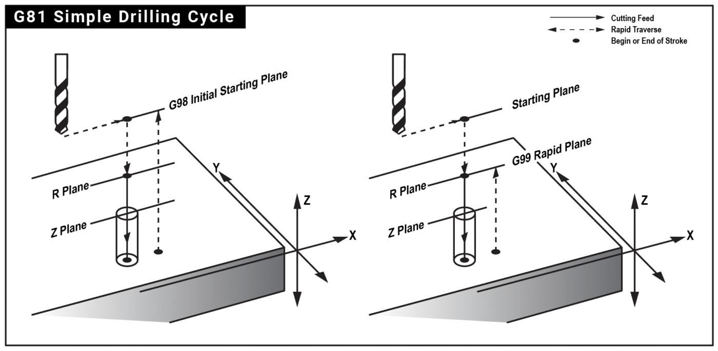
What the G81 Cycle Does
G81 is the simplest drilling canned cycle. It rapids to a safe clearance plane (R), feeds straight to the programmed depth (Z), and retracts—either back to the R-plane (G99) or all the way to the initial plane (G98). Use it for shallow to moderate depth holes where you do not need pecking or a dwell.
Syntax (Fanuc-Style)
G98/G99 G81 X__ Y__ Z__ R__ F__ L__ (modal)
Parameters
-
X, Y – Hole location.
-
Z – Final hole depth (typically negative in metric, e.g., Z-12.5).
-
R – Clearance plane above the part surface where cutting begins (e.g., R2.0).
-
F – Feedrate (mm/min or inch/min).
-
G98 – Retract to initial plane (the Z position before the cycle was called).
-
G99 – Retract to R-plane (faster, common when there are no clamps/obstacles).
- L → Number of cycle repetitions
Modal behavior: Once issued, G81 stays active. Every subsequent line with a new X/Y repeats the same Z, R, and F until G80 (cancel canned cycle) or another canned cycle is commanded.
Motion Sequence
-
Rapid (G0) to the current X/Y and to R height.
-
Feed (G1) from R down to Z.
-
Retract: G99 returns to R; G98 returns to the initial Z plane.
No dwell & no peck: If you need a dwell at the bottom, use G82. For deep holes or chip control, use G83 (peck drilling).
Example 1: Safe Programming Pattern (Recommended)
Always start a drilling section with a safe line to clear previous modes:
N10 G17 G40 G49 G80 G90 (XY plane, cancel CRC, cancel length comp, cancel cycles, absolute)
Set work and tool data, then call the cycle:
Notes
- G99 used so the tool retracts only to R2. If clamps are high or you need to clear features, swap to G98 before tight areas.
- Z-12.5 includes a small breakthrough for a 12 mm plate—adjust per material/fixture.
Example 2: Using G98 to Clear Clamps
Example 3: Fast Hole Patterns with Incremental XY
A common technique is to keep Z & R from the modal G81, then step X/Y incrementally for patterns. Use G90 to program the cycle (so Z is absolute), then switch XY to incremental with G91.
Tip: While XY are incremental here, Z and R from the modal G81 remain unchanged. Always return to G90 before leaving the section.
Quick Checklist Before Running G81 Cycle
-
Tool & Spindle: Correct drill size, spindle direction (M3/M4), RPM, and coolant (M8 if required).
-
Offsets: Right work offset (G54–G59) and tool length offset (G43 H__) active.
-
Cycle Parameters: R-plane above the surface, Z-depth below it, feedrate (F) correct for material.
-
Retract Choice: G98 if clamps/fixtures are in the way, G99 for faster cycles.
-
Safety: Confirm clearance around clamps, fixtures, and part features.
-
Simulation: Run a dry-run or graphics simulation above the part before actual machining.
-
Cancel Cycle: Always end the drilling section with G80 to prevent unintended drilling.
When Not to Use G81
-
Need a bottom dwell → use G82.
-
Need chip breaking or deep-hole strategy → use G83.
-
Need tapping/threading → use G84 (or rigid tapping option if available).
What the G82 Cycle Does
G82 is a drilling cycle similar to G81, but with an added dwell time at the bottom of the hole. After feeding down to the programmed depth (Z), the tool pauses for the specified time (P value) before retracting. This dwell improves hole accuracy, helps create a cleaner bottom surface, and is commonly used for countersinking and counterboring operations.
Syntax (Fanuc-Style)
G98/G99 G82 X__ Y__ Z__ R__ P__ F__ L__
Parameters
-
X, Y – Hole position.
-
Z – Final hole depth.
-
R – Clearance plane (start of drilling motion).
-
P – Dwell time at bottom (milliseconds on most Fanuc controls; some older controls use seconds).
-
F – Feedrate.
-
G98 – Retract to initial plane.
-
G99 – Retract to R-plane.
- L → Number of cycle repetitions
Difference vs. G81: The only extra parameter is P (dwell). The cycle motion is identical otherwise.
Motion Sequence
-
Rapid to R-plane.
-
Feed to Z-depth.
-
Pause (dwell) for programmed P time.
-
Retract: either to R-plane (G99) or initial plane (G98).
Example 1: Countersinking Holes
In this example:
- The drill rapids to R2.0, feeds to Z-7.5, then dwells 500 ms (0.5 sec) before retracting.
- The dwell ensures a smooth countersink bottom.
Example 2: Counterboring With Higher Retract
Feeds, Speeds & Dwell Tips
-
Dwell (P): Start with 300–500 ms for countersinks. Increase for larger tools or harder materials.
-
Feedrate: Use recommended drilling/countersinking feeds—too slow may cause chatter, too fast can damage edges.
-
Coolant: Strongly recommended, as the tool remains cutting during dwell.
-
Chip Control: G82 is not ideal for deep holes—use G83 instead.
When to Use G82
-
Countersinking.
-
Counterboring.
-
When a flat-bottom finish is required.
-
For precision holes needing consistent depth.
When Not to Use G82
-
Deep-hole drilling (use G83).
-
Tapping/threading (use G84).
-
Shallow, quick holes without dwell (use G81).
Common Mistakes & How to Avoid Them
-
Forgetting P: Without a dwell value, some controls may alarm, or no dwell will occur.
-
Too long P: Excess dwell may overheat the tool.
-
Forgetting G80: Always cancel the cycle when done.
-
Wrong plane: Stay in G17 for vertical drilling on VMCs.
Quick Checklist Before Running G82 Cycle
-
Tool & Spindle: Correct countersink/counterbore tool, spindle speed, direction (M3/M4), and coolant (M8).
-
Offsets: Ensure proper work offset (G54–G59) and tool length offset (G43 H__).
-
Cycle Parameters: Verify Z-depth, R-plane, and feedrate (F).
-
Dwell (P): Set appropriate dwell time (e.g., 300–500 ms for countersinking). Avoid too long a dwell.
-
Retract Mode: Choose G99 for fast retract to R-plane, G98 if clamps or obstacles are in the way.
-
Safety Check: Confirm clearance around fixtures and part features.
-
Cycle Cancel: Always end with G80 after drilling section.
-
Simulation: Perform a dry run or graphics simulation before actual machining.
The G83 canned cycle is used for deep hole drilling where chips must be cleared in steps (pecks) to prevent tool breakage. Unlike G81 (simple drilling) and G82 (drilling with dwell), G83 drills in repeated pecks, retracts slightly to break and clear chips, and then continues until the final depth is reached.
G83 Syntax
Parameters:
-
X, Y → Hole location coordinates
-
Z → Final drilling depth
-
R → Reference (retract) plane
-
Q → Peck depth (amount drilled per step)
-
F → Feedrate
-
G98 – Retract to initial plane.
-
G99 – Retract to R-plane.
- L → Number of cycle repetitions
Working Principle of G83
-
Drill feeds down by depth Q (peck amount).
-
Tool retracts above the cutting face (usually to R-level or slightly above the last cut) to break chips.
-
Drill feeds again another Q deeper.
-
This repeats until the programmed Z-depth is reached.
-
At the end, the drill retracts fully to the R plane.
This method prevents long chips from sticking to the drill and avoids excessive tool load, especially in deep holes or tough materials.
Example Program
N20 G90 G54 G00 X20 Y20 (Position to hole center)
N30 G43 H05 Z100. M03 (Tool length & Spindle On)
N40 G98 G83 X20 Y20 Z-40. R2. Q5. F120.
N80 G80 (Cancel canned cycle)
N90 G00 Z100. (Safe retract)
N100 M30
Explanation:
- Drill at position X20 Y20
- Drill final depth Z-40
- R2. → Retract plane = 2 mm above surface
- Q5. → Drill in 5 mm steps
- F120. → Feedrate = 120 mm/min
- G98 → Return to initial plane after drilling (use G99 if returning only to R plane).
Key Differences from G81 & G82
-
G81: Simple drilling, no chip breaking.
-
G82: Drilling with dwell at bottom.
-
G83: Deep drilling with pecking and chip clearing.
Quick Checklist Before Running G83 Cycle
-
Confirm Q (peck depth) is smaller than drill flute length.
-
Set proper R level to avoid tool crashes.
-
Use G98/G99 correctly (initial vs R plane return).
-
Choose suitable feedrate to match material & drill size.
-
Simulate toolpath in CAM/control to check retractions.
The G73 high-speed peck drilling cycle is specifically designed for VMC operations to increase productivity. Unlike deep-hole drilling cycles that retract to the reference plane, G73 performs a small, rapid retract to break the chip, allowing for significantly faster cycle times in materials that produce stringy chips or when drilling medium-depth holes.
G73 Syntax
G98/G99 G73 X_ Y_ Z_ R_ Q_ F_ L_
Parameters:
-
X, Y → Hole location coordinates
-
Z → Final drilling depth
-
R → Reference (retract) plane
-
Q → Peck depth (depth of each cutting increment)
-
F → Feedrate
-
G98 – Retract to initial plane.
-
G99 – Retract to R-plane.
- L → Number of cycle repetitions
Working Principle of G73
-
The tool rapids to the R plane.
-
The drill feeds down by the Q value.
-
The tool performs a small, rapid retract (a fixed parameter in the control) to break the chip.
-
The tool rapids back down to a position slightly above the previous depth and resumes feeding.
-
This process repeats until the final Z depth is reached.
-
The tool retracts at rapid speed to the R plane.
N10 T02 M06 (Drill Tool Call)
N20 G90 G54 G00 X20. Y20. (Move to first hole position)
N30 G43 H02 Z50. M03 S1500 (Tool length offset, spindle 1500 RPM)
N40 G98 G73 X20. Y20. Z-25. R2. Q5. F200. (Drill cycle)
N50 X-20. Y20.
N60 X-20. Y-20.
N70 X20. Y-20.
N80 G80 (Cancel canned cycle)
N90 G00 Z50. (Safe retract)
N100 M30
Explanation:
-
Hole location: The cycle executes at four positions (X50, Y50 through X50, Y100).
-
Z-25.: Total depth of the hole is 25 mm.
-
R2.: Retract plane is set 2 mm above the workpiece surface.
-
Q5.: The drill pecks in 5 mm increments, breaking the chips at each step.
-
F200.: The feedrate is set to 200 mm/min.
Important Notes
-
Chip Breaking: G73 is primarily for breaking chips, not for deep-hole chip removal. For very deep holes, use G83 to ensure chips are cleared from the hole.
-
Parameter Reliance: The “small retract” distance is typically determined by a machine parameter (consult your manufacturer’s manual).
-
Coolant: Because the tool stays in the hole, the use of high-pressure flood coolant or through-spindle coolant is highly recommended to flush out the broken chips.
-
Modal Status: Like other canned cycles, G73 is modal; it remains active until canceled by G80 or another canned cycle.
Quick Checklist Before Running G73
-
Check the Q value: Ensure your peck depth is appropriate for your drill diameter and material type.
-
Verify R plane: Confirm the R plane is high enough to clear any obstructions, but not so high that you waste cycle time.
-
Coolant Flow: Ensure your coolant nozzles are positioned to flush the chips out of the hole efficiently.
-
Drill Sharpness: Ensure the drill is sharp to prevent work hardening, especially in materials like stainless steel.
When standard tapping is insufficient for deep holes, many Fanuc programmers use the G84 Peck Tapping Cycle. While some controllers utilize specialized codes (like G84.2), the standard G84 can be configured for pecking by including a Q value (peck depth). This allows the tap to enter the hole in increments, breaking chips as it goes, which is vital for maintaining thread integrity in deep, blind holes.
G84 Syntax (Peck Tapping)
G98/G99 G84 X_ Y_ Z_ R_ Q_ F_ L_
Parameters:
-
X, Y → Hole location coordinates
-
Z → Final thread depth
-
R → Reference (retract) plane
-
Q → Peck increment (depth of each tapping step)
-
F → Feedrate (must equal tap pitch × spindle speed)
-
G98 – Retract to initial plane.
-
G99 – Retract to R-plane.
- L → Number of cycle repetitions
Working Principle of G84 Peck Tapping
-
The tool rapids to the R plane.
-
The spindle rotates clockwise (M03), and the tap feeds into the hole by the depth specified in Q.
-
Upon reaching the first peck depth, the spindle reverses (M04) and retracts slightly to break the chip.
-
The spindle then reverses again (M03) to continue feeding to the next increment.
-
This process repeats until the final Z depth is reached.
-
At the bottom, the spindle automatically reverses (M04) and retracts at the synchronized feedrate back to the R plane.
Example Program
N10 T08 M06 (Tap Tool Call)
N20 G90 G54 G00 X20. Y20.
N30 G43 H08 Z100. M03
N40 S500 M29 (500 RPM)
N50 G98 G84 X20. Y20. Z-30. R2. Q5. F625.
N60 G80 (Cancel canned cycle)
N70 G00 Z100.
N80 M30
Explanation:
-
Q5.: The tap enters 5 mm, breaks the chip, and continues.
-
F625.: Calculated as 1.25mm (pitch) x 500 RPM = 625 mm/min.
-
Synchronization: The machine maintains the feed/spindle relationship during every peck, ensuring the thread path is not ruined during the retract-and-re-entry steps.
Important Notes
-
Rigid Tapping (M29): On many modern Fanuc VMCs, you must command M29 S500 before the G84 block to engage the Rigid Tapping mode. Without this, the machine may not correctly synchronize the spindle encoder, which is catastrophic when pecking.
-
Q-Value Logic: The Q value must be a positive number representing the incremental depth. Ensure the total depth Z is divisible by Q for even peck distribution.
-
Chip Clearance: Unlike G83 drilling, G84 peck tapping does not retract to the R-plane during the pecking phase. If chips are still binding, you may need to reduce the Q value to create smaller chips.
Quick Checklist Before Running G84 Peck Tapping
-
Verify M29: Did you include the M29 rigid tap command before the cycle?
-
Check Feed Calculation: Re-calculate Pitch x RPM to ensure your F value is perfect.
-
Tool Engagement: Ensure the tap has enough clearance to start the rotation before it engages the material.
-
Lubrication: Use high-quality tapping fluid; the multiple reversals increase heat and friction significantly compared to single-pass tapping.
While standard right-hand threads dominate mechanical engineering, specific rotating assemblies—such as automotive axles, bicycle pedals, and high-speed CNC spindles—require left-hand threads to prevent operational forces from accidentally loosening the fasteners.
To safely and efficiently cut these specialized reverse threads on a Vertical Machining Center, we use the G74 Left-Hand Tapping Cycle. Just like the standard $G84$ cycle, the $G74$ cycle can be configured for single-pass tapping or transformed into a peck-tapping sequence by simply adding a $Q$ parameter to break up sticky chips in deep, blind holes.
G74 Syntax (Left-Hand Tapping)
G98/G99 G74 X_ Y_ Z_ R_ Q_ F_ L_
Parameters:
-
X, Y → Hole location coordinates
-
Z → Final thread depth
-
R → Reference (retract) plane
-
Q → Peck increment (depth of each tapping step)
-
F → Feedrate (must equal tap pitch × spindle speed)
-
G98 – Retract to initial plane.
-
G99 – Retract to R-plane.
- L → Number of hole repetitions
⚙️ The Critical Mechanical Difference: G74 vs. G84
Understanding the exact tool movement and spindle synchronization of the G74 cycle is vital to prevent catastrophic tool damage on the shop floor:
-
The tool positions directly over the hole (X, Y) and rapids down to the safe R-plane.
-
The Entry Phase: When Rigid Tapping (M29) activates the cycle, the spindle starts spinning counter-clockwise (M04) as the Z-axis feeds down into the hole.
-
The Chip Break (If Q is used): Upon reaching the specified $Q$ depth step, the controller momentarily reverses the spindle clockwise (M03) to break the thread chip before reversing back to M04 to continue cutting.
-
The Bottom Reversal: Once the tool reaches the final Z depth, the spindle automatically reverses to clockwise (M03) to back out smoothly, perfectly tracking the left-hand thread lead.
-
After exiting the hole completely, the spindle shifts back to its normal state, ready for the next position.
Here is a practical program segment demonstrating how to safely execute a rigid, left-hand M12 × 1.75 LH thread to a depth of 30mm using an operational spindle speed of 400 RPM:
Example Program
(G74 LEFT HAND TAPPING EXERCISE)
G90 G54 G21 G17 G80 G49 ; (Safe Startup Block: Absolute, Metric, Cancel Active Cycles)
T09 M06 ; (Tool Change: Select M12 Left-Hand Tapping Tool)
G00 X20.0 Y20.0 ; (Rapid position to the first hole center)
G43 H09 Z100.0 M08 ; (Activate Tool Length Offset, Move to safe Z clearance, Coolant ON)
(— ENGAGE RIGID TAPPING MODE —)
N40 S400 M29 ; (Lock Spindle Encoder at 400 RPM – Synchronizes Feed & Speed)
(— ACTIVATE G74 REVERSE PECK TAP CYCLE —)
N50 G98 G74 X20.0 Y20.0 Z-30.0 R3.0 Q6.0 F700.0 ; (Executes G74: Enters with M04, Pecks 6mm deep, Reverses with M03 to break chips, Exits cleanly)
G80 G00 Z100.0 M09 ; (CANCEL CANNED CYCLE – IMMEDIATELY UNLOCKS SPINDLE DIRECTION)
G28 G91 Z0 M05 ; (Return Z-axis home to reference zero, Turn Spindle OFF)
M30 ; (Program End & Rewind)
🧮 Technical Calculations Behind the Example:
-
Feed Rate (F): Calculated precisely as 1.75 mm (Pitch) x 400 RPM = 700 mm/min.
-
Synchronization: Because M29 locks the axis feed to the spindle position, the machine maintains perfect pitch coordination during entry, chip breaks, and reversal steps, entirely eliminating cross-threading risks.
⚠️ Important Shop Floor Notes
🚨 THE SPIRAL FLUTE WARNING FOR LH TAPS:
When purchasing tools for left-hand operations, you cannot use standard right-hand spiral-pointed or spiral-fluted taps. Standard spiral flutes are designed to lift chips out while rotating clockwise (M03).
Running a right-hand geometry tap counter-clockwise (M04) inside a G74 cycle will force the chips downward into the hole, causing the tap to bind, jam, and snap almost instantly. Always verify your tool is explicitly ground as a Left-Hand Tap.
-
M29 Pre-Call Requirement: Just like right-hand tapping, you must command the M29 Sxxx synchronization lock on the line directly preceding your G74 block to avoid running in floating-holder mode.
-
Avoid Manual M04 Calls on the Startup Line: Do not put an M04 command directly on your tool call or speed lines (N40 S400 M04). Let the G74 canned cycle command handle the spindle inversion automatically when it reaches the R-plane to prevent the tool from spinning backwards during rapid movements.
📋 Quick Checklist Before Pressing Cycle Start
Before executing your G74 left-hand tapping program on live stock, physically verify these items:
-
Confirm Left-Hand Tool Geometry: Visually check the tap flutes under a light to verify that the cutting edges are ground specifically for counter-clockwise rotation.
-
Verify M29 Alignment: Ensure your M29 rigid tap command is typed with the correct matching spindle speed code right above the cycle block.
-
Double-Check Feed Calculation: Re-multiply your left-hand pitch by the programmed RPM (Pitch x RPM = F). A single typo here will destroy both the workpiece and the tool.
-
Ensure Clear Bottom Clearance: Left-hand taps accumulate chips differently. Ensure your pre-drill depth is a minimum of 5mm to 8mm deeper than your target thread Z-depth to account for chip accumulation at the bottom of a blind hole.
When machining critical engine blocks, gear housing alignment bores, or high-precision press-fit holes, standard reaming or drilling cycles cannot deliver the required dimensional accuracy or mirror-like surface finish. For these high-stakes operations, programmers rely on a precision boring bar paired with the G76 Fine Boring Cycle.
The biggest challenge with standard boring commands (like G85 or G86) is that the cutting tip remains in direct contact with the finished metal wall while retracting back out of the hole. This leaves an ugly scratch or tool mark down the entire bore length.
The G76 cycle eliminates this flaw entirely by performing a synchronized tool-tip shift before retracting, guaranteeing a flawless, scratch-free surface finish.
📐 G76 Syntax (Fine Boring Format)
To execute a synchronized fine boring sequence on a Fanuc control panel, structure your code block as follows:
G98/G99 G74 X__ Y__ Z__ R__ Q__ F__ L__
🔍 Parameter Breakdown
-
X, Y: Centerline coordinate positions of the targeted hole.
-
Z: Final total depth of the finished bore (entered as a negative value, e.g., Z-40.0).
-
R: Reference plane (the safe clearance position right above the material face where cutting feed begins).
-
Q: The Shift Amount. This defines the exact incremental distance the boring bar moves away from the finished wall at the bottom of the hole before retracting (e.g., Q0.2 shifts the tool back by 0.2mm).
-
F: The cutting feed rate (mm/min). Fine boring utilizes a slow, controlled feed rate to ensure surface perfection.
-
G98 / G99 — Retract Selection:
-
G98: Retracts the tool completely back to the initial starting height clearance plane between separate holes to navigate safely around fixture components.
-
G99: Retracts the tool only to the safe R-plane between holes to optimize cycle efficiency.
-
-
L / K: Number of consecutive hole repetitions for grid patterns.
⚙️ How the G76 Cycle Works on the Shop Floor
The physical execution of a fine boring cycle follows a strict, highly controlled sequence to protect the finished bore surface:
-
The boring bar rapids directly over the hole coordinates (X, Y) and drops to the safe R-plane.
-
The tool feeds down into the hole at the programmed cutting speed (F) to machine the diameter down to the final Z depth.
-
Spindle Orientation Lock: At the absolute bottom of the hole, the spindle stops spinning completely and executes a precise Spindle Orientation Command (M19). This locks the spindle at an exact degree angle so the machine knows exactly which way the tiny cutting tip is facing.
-
The Shift Displacement: The VMC control panel slides the entire spindle housing slightly in the opposite direction of the tool tip by the exact distance specified in the Q parameter. This pulls the cutting edge away from the freshly machined wall, creating a clean physical air gap.
-
The tool rapids cleanly out of the hole to either the G98 or G99 clearance plane without touching the metal.
-
At the safe clearance plane, the spindle shifts back to the hole centerline, turns the spindle back ON clockwise (M03), and rapids to the next coordinate.
💻 Real-World G-Code Application Example
Here is a practical program segment demonstrating how to finish-bore a highly precise ⌀20mm press-fit bearing pocket down to a depth of 35mm using a spindle speed of 800 RPM:
O1008 (G76 FINE BORING ACADEMY EXERCISE)
G90 G54 G21 G17 G80 G49 ; (Safe Startup Block: Absolute, Metric, Cancel Active Cycles)
T10 M06 ; (Tool Change: Select Precision Boring Bar Tool)
G00 X50.0 Y50.0 ; (Rapid position to the first hole center)
G43 H10 Z50.0 M08 ; (Activate Tool Length Offset, Move to safe Z clearance, Coolant ON)
(— ACTIVATE G76 FINE BORING CYCLE —)
N40 S800 M03 ; (Start Spindle Clockwise at 800 RPM)
N50 G99 G76 X20.0 Y20.0 Z-35.0 R2.0 Q0.2 F80.0 ;
(Executes G76: Bores to Z-35., stops spindle, orientates, shifts away 0.2mm, rapids out)
G80 G00 Z100.0 M09 ; (CANCEL CANNED CYCLE – RESETS SPINDLE SHIFT MODES)
G28 G91 Z0 M05 ; (Return Z-axis home to reference zero, Turn Spindle OFF)
M30 ; (Program End & Rewind)
🧮 Technical Calculations Behind the Example:
-
The Q0.2 Parameter: Shifting by 0.2mm is just enough to completely clear the cutting tip from the wall without requiring a large displacement that could cause the boring tool body to scrap the opposite side of the hole.
-
The F80.0 Parameter: Fine boring requires a low feed rate coupled with a matching spindle speed to eliminate chatter and ensure a flawless surface roughness value ($Ra$).
⚠️ Important Shop Floor Notes
🚨 THE SEVERE DANGER OF AN INCORRECT SHIFT DIRECTION:
The G76 cycle assumes your tool tip is loaded into the spindle facing a specific quadrant direction (usually matching the machine’s factory default parameters, such as the +X or -X direction).
If a machinist mounts the boring bar into the tool holder backwards (180° out of position), the machine will orient the spindle and shift the tool INTO the finished wall instead of away from it. This will instantly gouge the surface, ruin the component, and can crush the expensive carbide boring tip. Always visually confirm your tool tip alignment matches your machine parameter settings before running.
-
Parameter Divisibility: Unlike a drilling cycle where Q cuts progressively, the Q in a G76 cycle is a single, hard-coded shift value executed only at the very bottom of the hole. Never enter a negative or excessive shift number.
-
Coolant Control: Ensure your coolant lines are clean and providing strong flow to flush out any microscopic chips before the spindle halts at the bottom of the bore.
📋 Quick Checklist Before Pressing Cycle Start
Before executing your G76 fine boring program on a live piece of material, physically verify these four items:
-
Verify Tool Tip Orientation: Double-check your machine manual or perform a dry-run test in the air to ensure the boring bar tip shifts away from the wall correctly during spindle orientation (M19).
-
Confirm Q-Value Scale: Ensure your Q value is calculated correctly in your code layout. A value like Q2.0 instead of Q0.2 will command a massive 2mm shift, crashing the backside of the boring bar tool steel straight into your finished part.
-
Pre-Bore Tolerance Check: Fine boring bars are strictly meant to remove a tiny finishing allowance (typically between 0.15mm to 0.3mm on the diameter). Ensure your pre-drilling or rough-pocketing operations left the correct amount of material.
-
Inspect Carbide Edge Integrity: Look at the cutting nose radius under magnification. Any microscopic chipping on the tool edge will ruin the surface finish, regardless of how perfectly your G76 cycle runs.